Non-Linear Compensation
Overview
Non-linear compensation corrects the non-linear motion errors of each axis across the full travel range, including X, Y, and Z axis non-linear compensation as well as perpendicularity compensation between axes. This is a critical step for ensuring high-precision measurements.
Axis Non-Linear Compensation
The following uses the X axis as an example. The procedure is the same for the Y and Z axes — simply align the scale parallel to the corresponding axis.
Prerequisites
- Prepare a standard scale ruler
- Obtain controller modification permission from your equipment supplier
Steps
Step 1: Position the Scale
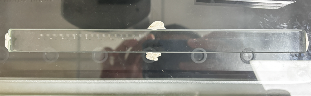
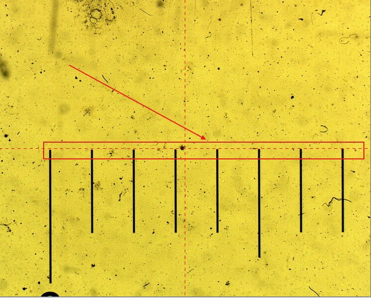
Place the scale on the stage and align it parallel to the axis requiring compensation. For X-axis compensation, the scale direction should be parallel to the X axis.
Step 2: Open Non-Linear Correction
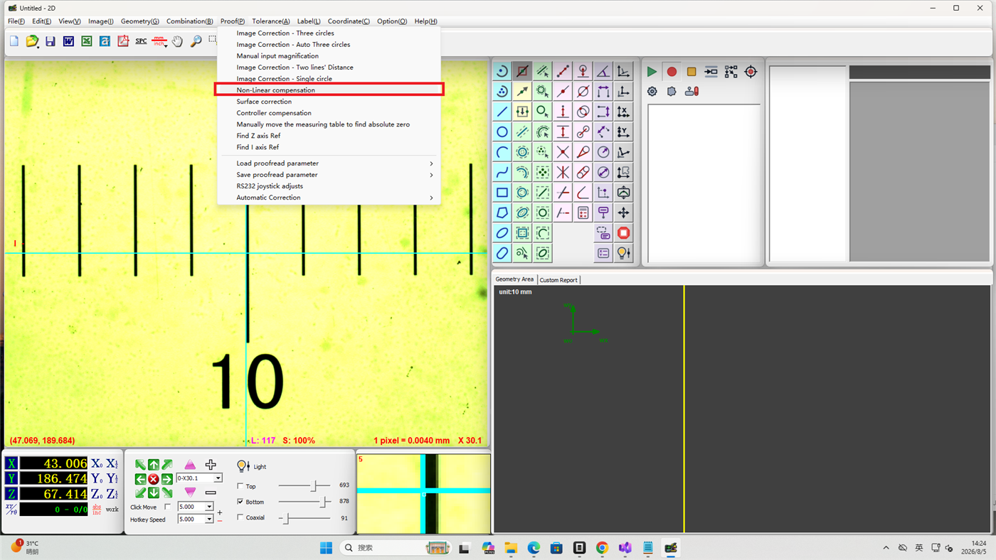
Click Calibration in the menu bar, then select Non-Linear Correction.
Step 3: Configure Compensation Parameters
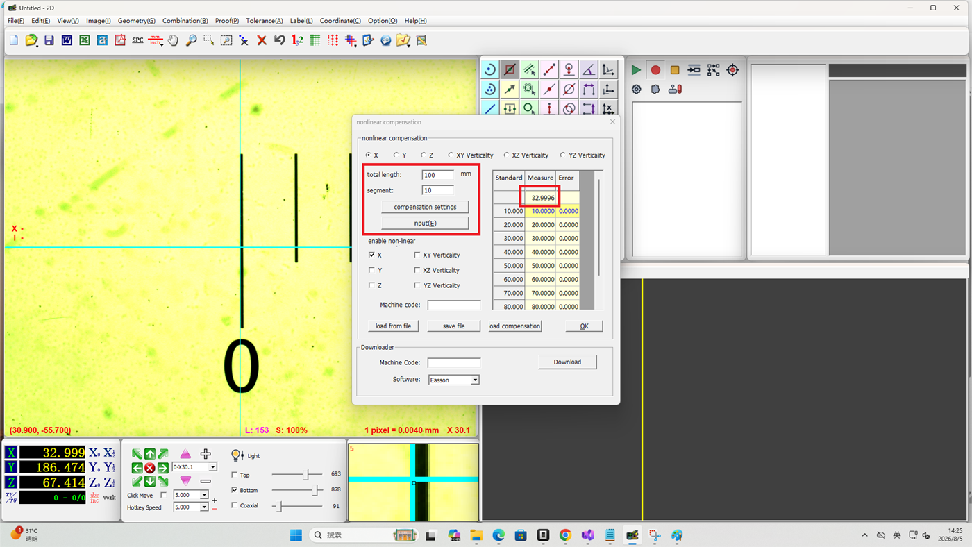
- Enter the total compensation length and the number of compensation segments
- Click Set Compensation — the software will automatically generate a data template
- Move the stage to the compensation start position
- Click Input — the measured value column will display the actual X-axis coordinate (e.g. 66.8823)
Step 4: Complete Segment by Segment
- Following the data template, successively position the stage at each compensation point on the scale
- Click Input at each position — the measured value column will display the relative X-axis coordinate (e.g. 9.9926)
- Repeat this process for all data segments
- After completing the entire data table, click OK
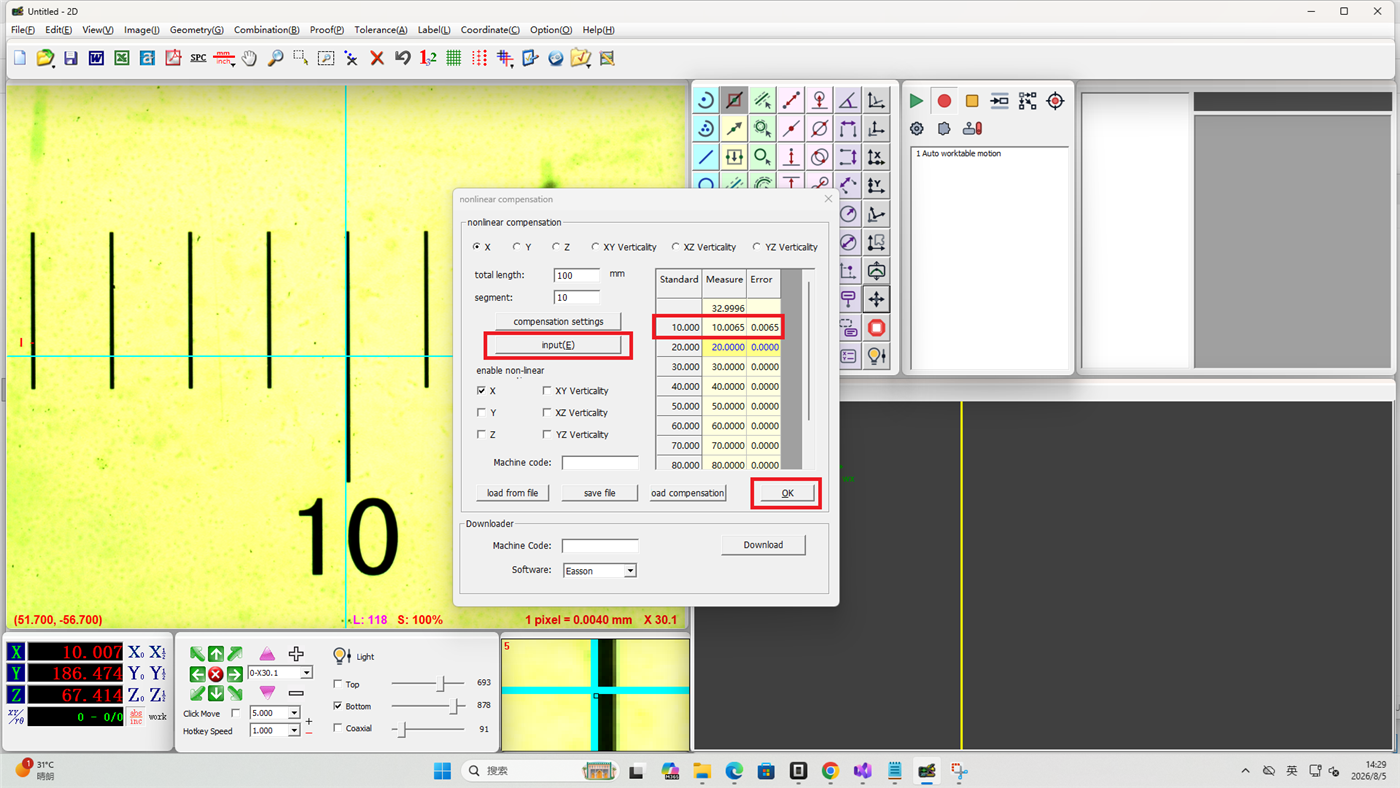
The procedure for Y-axis and Z-axis non-linear compensation is the same as above. Ensure the scale is aligned parallel to the Y and Z axes respectively.
Perpendicularity Compensation
Perpendicularity compensation corrects the angular errors between axes, including XY perpendicularity, XZ perpendicularity, and YZ perpendicularity.
Step 5: Download Perpendicularity Compensation Data
Perpendicularity is compensated by an engineer and saved on the server. Enter the machine serial number to download the compensation data.
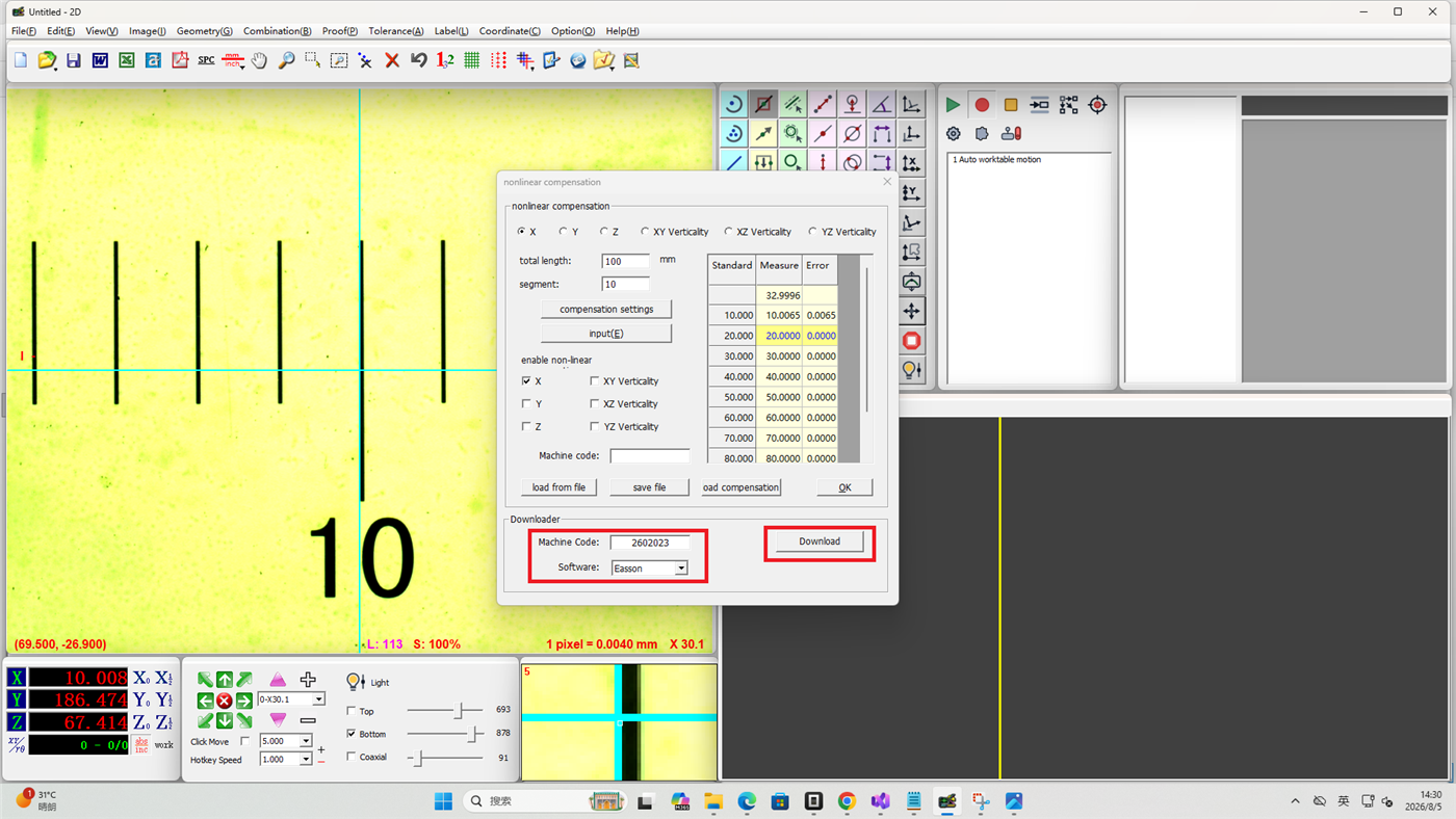
Step 6: Load the Compensation File
Click Load Compensation File to load the perpendicularity compensation data.
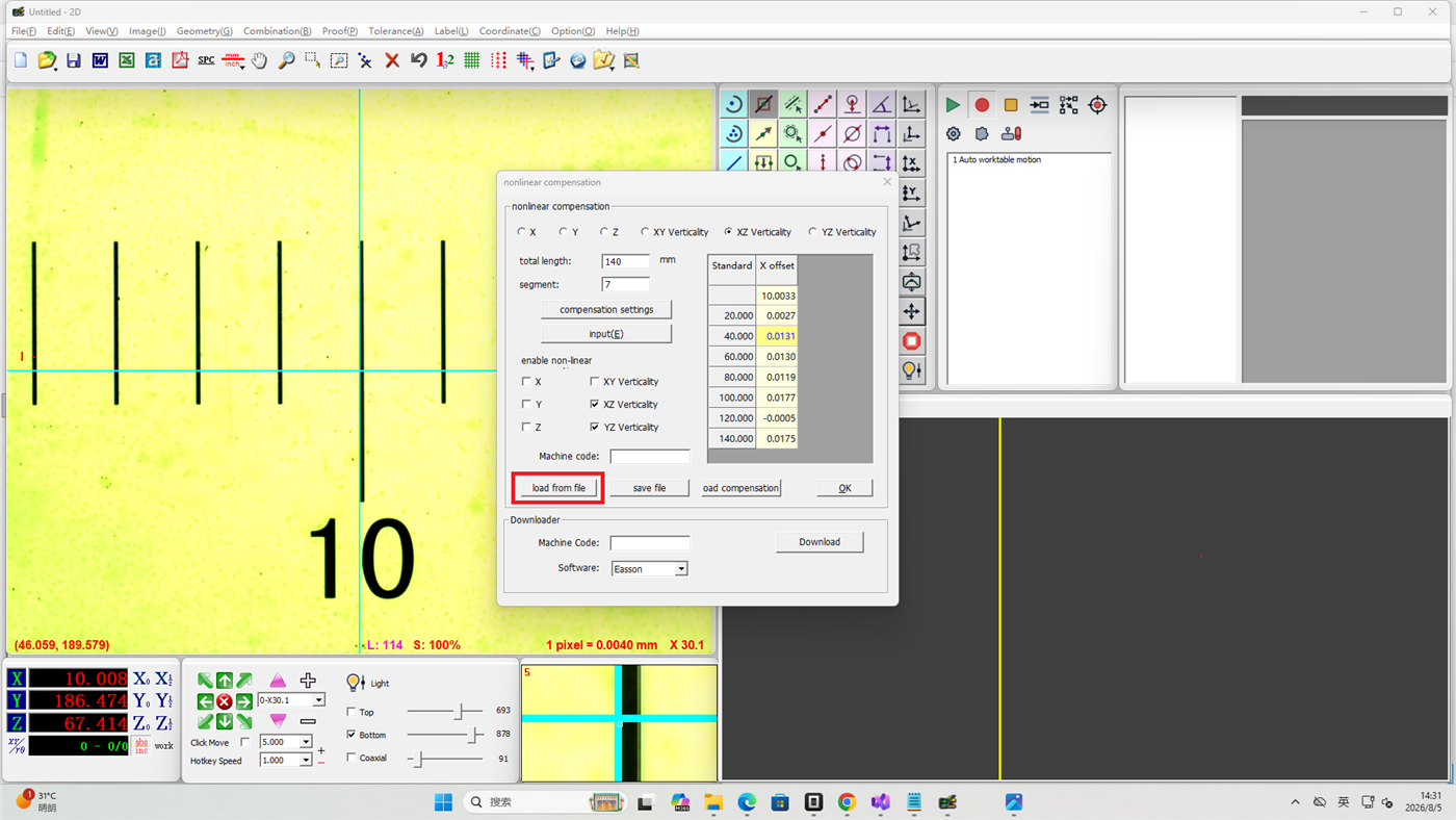
Notes
- Non-linear compensation involves modifying controller parameters — obtain permission from your equipment supplier
- The alignment between the scale and the axis directly affects compensation accuracy
- More compensation segments yield higher accuracy but require more steps to complete
- Perpendicularity compensation must be completed by an engineer and uploaded to the server in advance
- It is recommended to periodically check compensation results and recalibrate if necessary