Interface Overview
Overview
The main interface of Easson2D is divided into several functional areas, each with a distinct purpose that contributes to the measurement workflow. Familiarizing yourself with each area will help you get started quickly.
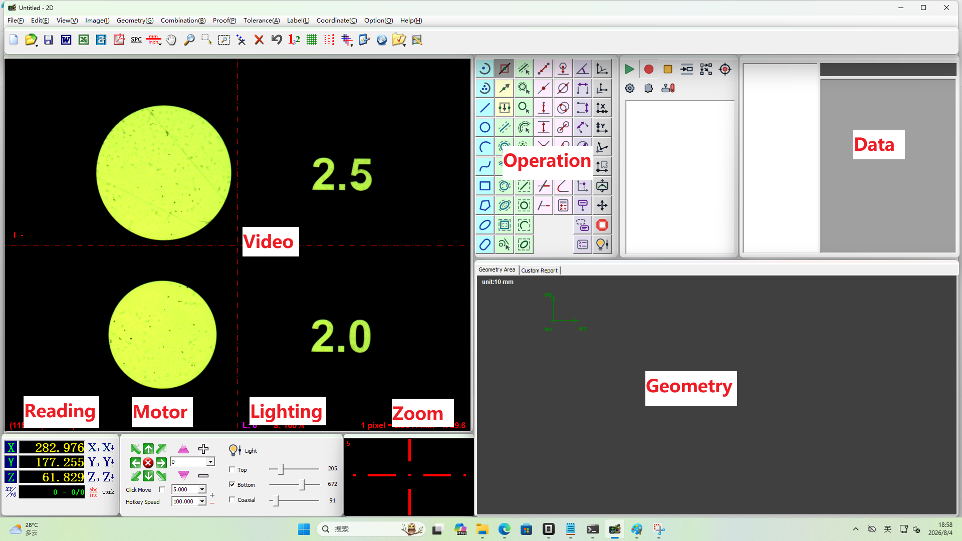
Interface Areas
Geometry Area
The Geometry Area is used for element dimensioning, tolerance calculation, coordinate system setup, and element construction.
- Apply dimensions and tolerances to measured elements
- Create and manage workpiece coordinate systems
- Generate new elements through geometric construction
Vision Area
The Vision Area is the central display region where you view workpiece images, control machine movement, and perform measurements.
- Displays real-time camera images of the workpiece
- Control stage movement by dragging or clicking with the mouse
- Perform point picking and measurements directly on the image
Motor Area
The Motor Area is used to configure parameters related to machine motion.
- Set stage movement speed
- Adjust step distance
- Control the direction and mode of each axis
Illumination Area
The Illumination Area is used to adjust the brightness of the machine light sources to obtain clear workpiece images.
- Independently adjust brightness for different light channels (top light, bottom light, etc.)
- Adapt lighting conditions based on workpiece material and surface finish
- Improve image contrast for better edge detection accuracy
Measurement Bar
The Measurement Bar is used to perform various measurement operations on the workpiece displayed in the Vision Area.
- Select measurement tools and modes
- Measure geometric elements such as points, lines, circles, and arcs
- Switch between manual and automatic measurement modes
Data Area
The Data Area stores measurement and calculation results, as well as saved measurement programs.
- View lists of measured elements and calculation results
- Manage measurement programs and parameter configurations
- Export measurement data
Magnifier
The Magnifier provides a localized zoomed view of the Vision Area for inspecting fine workpiece details.
- Displays a magnified image of the area near the cursor
- Assists with precise point picking and edge detection
Readout Area
The Readout Area displays the current electronic scale readings for the machine's center position.
- Shows real-time X, Y, and Z axis coordinates
- Helps verify the accuracy of the current measurement position
Notes
- The layout and arrangement of interface areas may vary depending on the software version and machine configuration
- Some areas may support resizing by dragging, allowing you to customize the layout to suit your workflow