Probe Point Measurement
Easson2D's Probe Point Measurement is used to obtain a spatial measurement point by contacting the probe with the workpiece surface.
During measurement, the software compensates for the probe ball radius according to the set compensation direction, and can optionally project the measurement result onto a specified plane. After the probe is triggered, Easson2D automatically generates the corresponding point element.
1. Select Probe Point Measurement
Click:
Probe Measurement → Probe Point Measurement
When entering this function for the first time, the Probe Point Measurement settings window appears.
The main settings are:
- Compensation direction
- Projection option
After configuring, click OK.
The current settings are retained until you re-enter the Probe Point Measurement command and modify them.
2. Set the Compensation Direction
Probe measurement returns the position where the probe ball contacted the workpiece, so the probe radius compensation must be applied according to the direction in which the probe contacts the workpiece.
The compensation direction specifies the plane direction of the point being measured, or a reference plane parallel to that surface.
For example, when measuring a horizontal surface in the XY direction, you can select:
XY Plane
Easson2D compensates the probe contact position according to the selected direction, giving the actual point position on the workpiece surface.
Therefore, the compensation direction should be selected according to the actual direction of the surface being measured.
3. Set the Projection Option
The projection option determines whether the measured point obtained after probe compensation is further projected onto a specified plane.
If you select:
None
the measured point position after compensation is retained.
If you need to project the measurement results uniformly onto a specified plane, select the corresponding projection method.
In general, if you only need the actual point on the workpiece surface, you can select None.
4. Probe a Point
After configuration, move the probe to the position to be measured.
Move the probe slowly so that the probe ball contacts the workpiece surface.
After the probe is triggered, Easson2D will:
- Acquire the current probe position.
- Apply probe radius compensation according to the compensation direction.
- Process the measured point according to the projection option.
- Automatically generate a point element.
You can then continue measuring other positions.
Basic Workflow
Probe Point Measurement can be summarized as:
Probe Measurement → Probe Point Measurement → Set the compensation direction → Set the projection option → Move the probe to contact the workpiece surface → Probe is triggered → A point is automatically generated
Requirements for the Measured Surface
Probe Point Measurement is mainly used to measure points on planes.
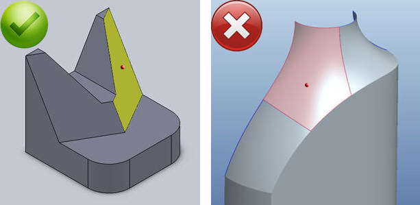
For example, to measure a point on plane A, first determine plane A, or establish a reference plane parallel to plane A, then apply probe compensation according to the direction of that plane.
Therefore, this function is suitable for:
- Points on horizontal planes
- Points on vertical planes
- Points on inclined planes
- Surface points aligned with an established reference plane
Probe Point Measurement is not suitable for directly measuring points on curved surfaces.
For cylindrical surfaces, circular arc surfaces, or other curved surfaces, use the corresponding probe geometric element measurement functions.