Verticality
Overview
Verticality evaluates the deviation of a measured element from an ideal 90° relationship with a datum element. In Easson2D, the system first establishes an ideal perpendicular reference based on the datum element, then calculates the distance from representative points on the measured element to that reference, and takes the maximum value within the effective evaluation length as the perpendicularity result.
Steps
Step 1: Click the Function Button
Click Verticality in the Tolerance menu to open the geometric tolerance dialog.
Step 2: Select Elements
Select line elements in the Vision Area or Geometry Area:
- The first click selects the measured element
- The second click selects the datum element
Step 3: Create Label (Optional)
To create a label, check Create Label before confirming. Left-click in the Vision Area or Geometry Area to place the annotation at the desired position.
Calculation Principles
The system first establishes an ideal perpendicular reference based on the datum element, then calculates the maximum deviation of the measured element from that ideal perpendicular reference.
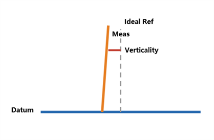
Common branches include: line-to-line, plane-to-plane, axis-to-plane, and plane-to-axis perpendicularity.
Formula
Given an ideal perpendicular reference line passing through A(x₁, y₁) and B(x₂, y₂), and a representative point P(x₀, y₀) on the measured line, the distance from P to the ideal reference line is:
d = |(y₂ - y₁)x₀ - (x₂ - x₁)y₀ + x₂y₁ - y₂x₁| / √[(y₂ - y₁)² + (x₂ - x₁)²]Verticality = max(dᵢ)
Example Calculation (Line-to-Line)
Given:
- Datum element: D1 = (0.000, 0.000), D2 = (20.000, 0.000)
- Measured element: M1 = (10.000, 0.000), M2 = (10.020, 25.000)
- Evaluation length L = 25.000 mm
Step 1: Establish the datum direction
The datum element is a horizontal line. The ideal perpendicular direction is vertical.
Step 2: Establish the ideal perpendicular reference
Through M1 = (10.000, 0.000), the ideal perpendicular reference line is: A = (10.000, 0.000), B = (10.000, 25.000), i.e. x = 10.000.
Step 3: Calculate distances
- M1 = (10.000, 0.000): d₁ = 0.000 mm
- M2 = (10.020, 25.000): d₂ = |10.020 - 10.000| = 0.020 mm
Step 4: Take the maximum
Verticality = max(0.000, 0.020) = 0.020 mm
Other Branches
- Axis-to-plane perpendicularity: Projects axis endpoints onto the datum plane and calculates the deviation
- Plane-to-axis perpendicularity: Projects representative points of the measured plane onto the datum axis and compares the maximum spread
Notes
- Both the measured element and the datum element must be line elements
- The selection order matters: select the measured element first, then the datum element
- Labels can be placed flexibly as needed